THE CHART RECORDER


The CAPTURE Chart Recorder displays a real-time graph of RAD7 data as it is recorded. As a radon test progresses, a set of virtual pens plot radon concentration, temperature, and humidity data on the right side of the display, while older readings scroll to the left.

The Chart Recorder contains a Button Bar for starting and stopping tests and configuring RAD7 settings. Below the Button Bar is a Status Display panel which indicates the current state of the RAD7. A nearby panel of Chart Recorder Controls is used to adjust the appearance and range of the Chart Recorder. These features and others are described in detail below.
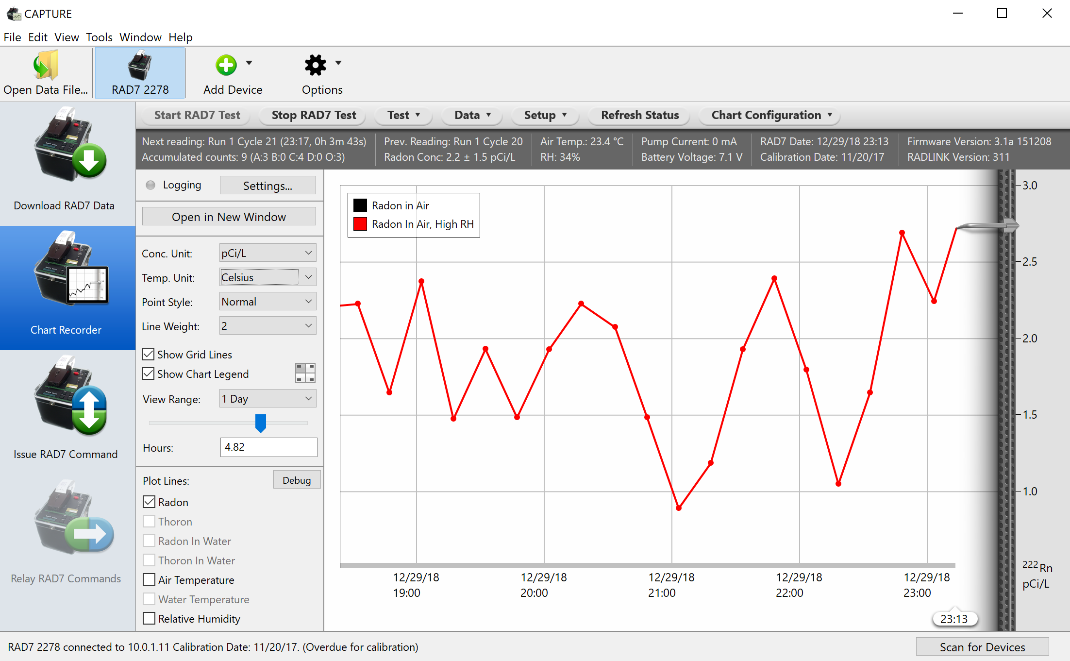

Figure 1: The CAPTURE Chart Recorder.

Chart Button Bar 

The Chart Recorder's Button Bar contains controls for starting and stopping the RAD7, configuring RAD7 and chart settings, and refreshing the Status Display and Chart.


Figure 2: The Chart Recorder Button Bar.
 

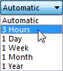
The Start RAD7 Test button begins a RAD7 test and initiates real time data tracking. This button has the same effect as selecting Test Start on the actual RAD7. Likewise, the Stop RAD7 Test button emulates the RAD7's Test Stop function.

The Test, Data, and Setup menus provide access to the set of commands available on the RAD7 itself, under menus of matching names. Selecting one of these commands will have the same result as entering the corresponding command on the physical RAD7. These commands are described in Chapter 2 of the RAD7 User's Manual. Note that menu commands ending with ellipses (...), such as "Units..." and "Clock..." will present dialog boxes for specifying command parameters, as shown in the Figures 3 and 4, below.

The Refresh Status Display button will update the statistics shown in the Chart Status Display, and will cause the Chart Recorder image to be refreshed. Normally this occurs automatically every 60 seconds, but the Refresh Status Display button is useful when an immediate status update is desired.

The Chart Configuration menu contains two commands: Logging Settings and Chart Parameters.

The Logging Settings command is used to configure the program to log Chart Recorder data to disk as it arrives. This is explained in the Logging Chart Recorder Data section, below.

The Chart Parameters command brings up the Chart Parameters Window, which is used to specify the Radon Measurement Method, which may be either Radon in Air, RAD AQUA, or Water Probe. If the RAD AQUA or Water Probe is selected, the Chart Recorder will be able to display radon in water data. Computing radon in water concentrations requires information about the water's salinity and temperature. The salinity is expressed in parts per thousand (‰). The temperature can be set to either the air temperature as recorded by the RAD7 (plus or minus a fixed offset), or to a fixed temperature value, expressed in either Fahrenheit or Celsius. The Chart Parameters Window is shown in Figure 5, below.


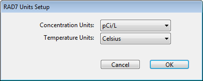
Figure 3: The Chart Recorder RAD7 Units Setup dialog.


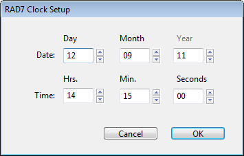
Figure 4: The Chart Recorder RAD7 Clock Setup dialog.


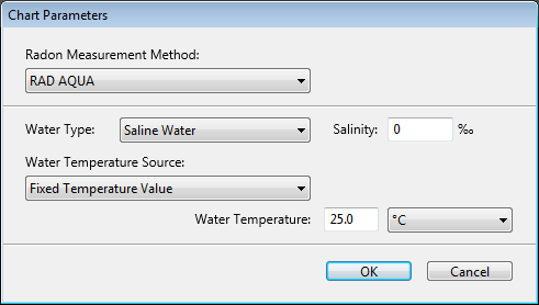
Figure 5: The Chart Parameters Window.

Chart Status Display

The Chart Status Display is a panel providing real-time statistics on the state of the RAD7, including the run and cycle numbers of the next RAD7 reading, the date and time of the next reading, the counts that have accumulated in each window since the last reading was recorded, and the previous reading's run number, cycle number, and radon concentration. Also included is the RAD7's current air temperature, relative humidity, pump current, and battery voltage, and the device's internal clock settings.

The Chart Status Display is automatically updated every five minutes, notwithstanding the immediate update that occurs when clicking the Refresh Status Display button. Each time an update is initiated, it takes about 5 seconds for the latest status information to be obtained and displayed. Updates are delayed while the RAD7 is busy printing cycle and run summaries.


Figure 6: The Chart Recorder Status Display.

Chart Recorder Controls  


To the left of the Chart Recorder is a panel of controls similar to those accompanying the Graph Window, but simplified in functionality. The use of each control is explained below:

Open As Graph Button

Click the Open as Graph button to view the content of the Chart Recorder in a Graph Window. This makes it possible to examine the data in more detail, apply corrections, and export it in a variety of formats.

Concentration Units Pop-Up Menu

Determines the unit of measurement used to denote radon concentrations on the chart. The available options include Automatic, Bq/L, Bq/m3, dpm/L, and pCi/L. The Automatic option causes radon concentrations to be presented in the unit to which the RAD7 has been set.

Temperature Units Pop-Up Menu

Determines the unit of measurement used to denote air temperatures on the chart. The available options include Automatic, Celsius, Fahrenheit, and Kelvin. The Automatic option causes temperatures to be presented in the unit to which the RAD7 has been set.

Point Style Pop-Up Menu

Determines the appearance of the data points on the chart. The options are Normal, Shapes, B&W (Black and White) Shapes, and Hidden. The B&W Shapes option causes the graph to be rendered in black and white.

Line Weight Pop-Up Menu

Determines the thickness of the chart lines, as measured in pixels. This value may range from 1 to 4, or the chart lines may be hidden. A thicker line may be easier to read, but is somewhat less precise than a single-pixel line.

Show Grid Lines Checkbox

Determines whether horizontal and vertical grid lines are visible on the chart.

Show Chart Legend Checkbox

Determines whether the legend is visible on the chart. The legend indicates the significance of the colors that appear on the chart. To the right of the Show Chart Legend Checkbox is a small control for setting the position of the Chart Legend. It may be placed in any of the four corners of the chart image.

View Range Pop-Up Menu

Determines the maximum visible time range supported by the View Range slider. If the View Range Pop-Up Menu is set to Automatic, the visible range is determined by the breadth of chart data. Other View Range options include 3 Hours, 1 Day, 1 Week, 1 Month, and 1 Year. When the View Range is changed, CAPTURE may obtain additional data from the RAD7 available to fill the available space.


Figure 7: The View Range Pop-Up Menu.

View Range Slider and Hours Field

The Visible Range slider zooms the Chart Recorder view in and out. When this slider is dragged all the way to the left, the entire collection of data is made visible. When the slider is dragged all the way to the right, only the most recently recorded data points remain visible. The Hours field can be used as an alternative to the slider: input the desired number of hours and press Enter to set the chart range. Note that the right edge of the chart always represents the current time.

Radon, Air Temperature, and Relative Humidity Checkboxes

These checkboxes determine whether radon, relative humidity, and air temperature points are visible on the chart. The radon concentration data that is plotted on the chart is always taken directly from the RAD7, with no corrections made with respect to spill, humidity, or other factors.

RAD7 Printer Present Checkbox

The RAD7 Printer Present checkbox is used to specify whether an infrared printer has been positioned on the RAD7. If this box is checked, CAPTURE will allow printing to proceed uninterrupted after each record is recorded. If this box is not checked, updates to the Status Display will be given higher priority, potentially interrupting end-of-cycle RAD7 printing operations.


Monitoring RAD7 Groups

The Chart Recorder is particularly useful for monitoring groups of RAD7s. RAD7 Groups are sets of RAD7s designated by the user whose data is averaged and displayed as a single chart. For best results the timing of the RAD7s in the group must be synchronized.

To configure a RAD7 group, first make sure at least two RAD7s are connected and that their icons are visible in the Main Window Toolbar. In the toolbar, select the Options Menu (which is labeled with a gear icon) and select Add RAD7 Group...

The Add RAD7 Group command creates a new RAD7 Group for the Chart Recorder and displays the RAD7 Group Configuration dialog, which which is used to specify the group's name and its member RAD7s. After the RAD7 Group has been configured, it will appear as an icon in the Toolbar, next to the other RAD7s. Selecting a RAD7 Group causes displays a chart representing an average of the data belonging to the member RAD7s.


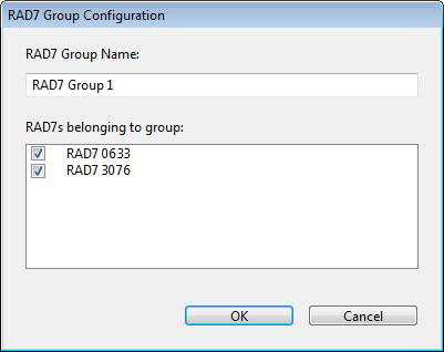
Figure 8: The RAD7 Group Configuration dialog

Details on adding, managing, and removing RAD7 Groups is available in the Toolbar Commands section.
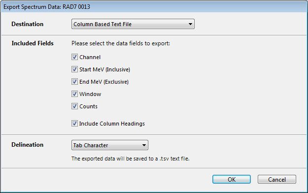

Logging Chart Data

When the Chart Recorder is active, chart data may be logged to disk in any of several formats. Clicking the Settings button, which is alongside the Logging indicator light to the left of the chart, brings up the Logging Settings dialog box, which is shown below.

Within the Logging Settings dialog box, the Select File Location button is used to specify the name and location of the logged data. The Log Supplementary Data checkbox controls whether the RAD7's printer output device information is saved to the log file in addition to the basic data. If this box is checked, a .r7cdt file with more complete records will be created. Otherwise, the data will be saved to a .r7raw file. The Log to Column Based Text File checkbox makes it possible to log a comma-delimited or tab-delimited text file, which may be opened as a spreadsheet for further analysis.

After specifying the desired settings, click the Start Logging button. The Logging light on the Chart Recorder will turn green to indicate that logging is active. It is possible to return to the Logging Settings dialog at any time by clicking the Settings button. If logging is active, it may be disabled with the Stop Logging button, found at the lower left corner of the Logging Settings dialog.

Upon disconnecting a RAD7 or exiting CAPTURE, the program will save any outstanding chart recorder data. This process will normally take several seconds, but may be canceled if it is necessary to exit CAPTURE immediately.

Note that even if logging is not specifically enabled, CAPTURE will maintain records of raw Chart Recorder data in the Preferences folder. These files can be revealed at any time by selecting Show Chart Recorder Logs from the File Menu.


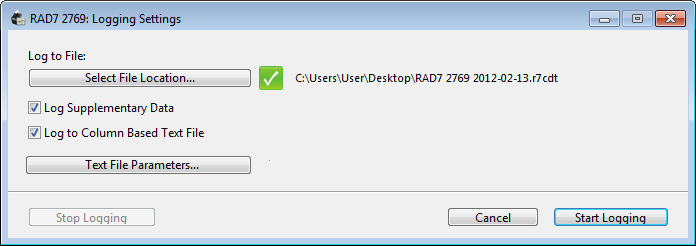
Figure 9: The Chart Recorder Logging Settings Dialog.


Chart Recorder Spectrum

When the Chart Recorder is visible, it is possible to display the Chart Recorder Spectrum Window, which contains a diagnostic histogram representing the cumulative spectrum for the selected RAD7. This histogram consists of 200 columns, each representing the number of counts that have accumulated within a corresponding 0.05MeV (50keV) spectrum channel. If the selected RAD7 uses RADLINK software version 0300 or newer, the spectrum data will comprise the current or most recently completed run. If the RAD7 uses an earlier version of RADLINK, such as version 0252, the spectrum will represent only the current cycle, and only then if the RAD7 is Live.

To display the Spectrum Window, choose Show Spectrum Window from the Window menu in the menu bar. The spectrum histogram image is automatically refreshed upon the completion of each RAD7 cycle.


Figure 10: The Chart Recorder Spectrum Window.

The spectrum data content can be exported to either a text file or the clipboard. To do this click the Export Spectrum Data button, found at the top of the Chart Recorder Spectrum Window. The exported data consists of 200 lines of text, one for each bar in the Cumulative Spectrum histogram. Each data line may contain up to five columns, as follows:

Channel: The channel number, ranging from 1 to 200.
Start MeV (Inclusive): The lower inclusive bound of the channel's energy range.
End MeV (Exclusive): The upper exclusive bound of the channel's energy range.
Window: The general category of the channel, for example, "218Po (A)", "216Po (B)", etc.
Counts: The number of counts recorded in the current channel.

These fields may be delimited by tab or comma characters. If the tab character is chosen, exported data files will use the .tsv file name extension, indicating Tab Separated Values. If the comma character is chosen, exported files will use the .csv extension, indicating Comma Separated Values. Either of these options allow the spectrum data to be opened in a spreadsheet or other tool for further analysis.

Figure 11: The Export Spectrum Data Window.